
An NFC Jukebox for the Kids
The jukebox is a small music box for children. It has no screen to scroll and no menu: you take a card from the pouch on its side, put it on the circle engraved on the top, and the album that belongs to that card starts playing. Five big buttons handle the volume, pause and the tracks, and a four-digit display shows the track number.
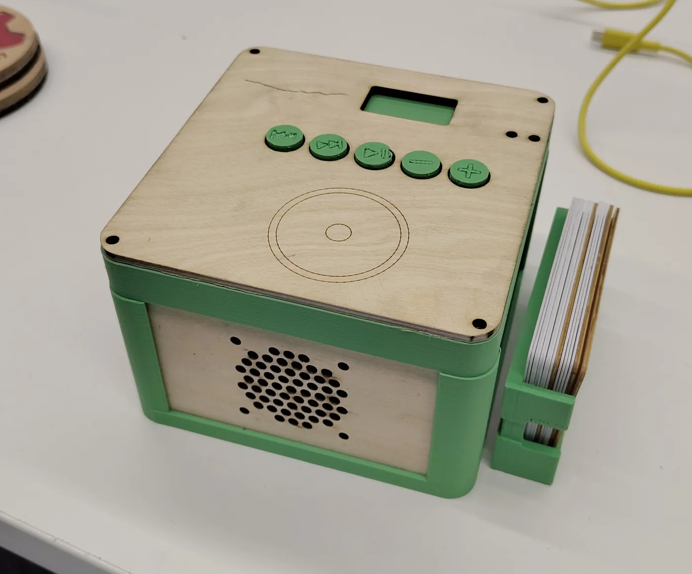
I built it mainly for my oldest kid, who is four and loves listening to music and stories. His little sister uses it too. I wanted a box I can put any music on, without depending on a cloud service or an account, that is unique, and that can keep evolving as the kids grow and as I think of new things to add.
We already had a Maiasaura, a commercial stories box, but to find anything he had to move through the whole catalog with next and previous buttons and a “change directory” button. That is not easy for a four-year-old, and he could not choose what he wanted to hear by himself. Here, each card is one album, so he picks the card and the music starts.
He also makes the cards his own. He puts stickers on them so he can recognize them easily. His favourite card in the morning is the debug card, which plays “Never Going Home” by Kungs, and he loves to play it at full volume.
Inside there is an ESP32-S3, an NFC reader, a DAC with a small speaker, an SD card and three 18650 cells. The albums live on a server in my lab, and the box only downloads an album the first time its card is tapped. After that it plays from the SD card, with or without Wi-Fi.
The project started at the end of 2025 with an Arduino firmware and a prototype with rotary encoders. This autumn I rewrote the firmware from scratch, redesigned the board and built a new, more child-proof case. This post goes through how it works, why the firmware had to be rewritten, what the rev 2.0 board changes, and how the case is generated from a script.
How it works
The box and the server only share a small HTTP API:
-
Tap. The PN532 reader, on I2C, sees a card and the firmware takes its UID.
-
Lookup. If the card is known in the
mapping.jsonfile on the SD card and its album is complete, playback starts at once, and the mapping is checked with the server afterwards. Otherwise the box joins the Wi-Fi and asksGET /api/v1/map/{uid}. An unknown card is recorded by the server and appears under Unmapped tags in the web interface, where I can assign it to an album.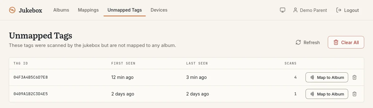
Unmapped tags: two cards the jukebox has scanned but that have no album yet. A click on Map to Album assigns one. The data on this screenshot is made up. -
Download. The firmware fetches the album’s
manifest.json, makes room on the card if needed by evicting the album that has not been played for the longest time, then downloads each track over HTTPS. Every track is checked against the SHA-256 in the manifest. -
Play. MP3s are decoded in software and sent over I2S to the DAC. At the end of the album the box goes back to idle.
The server is a FastAPI application with a Vue interface, deployed in the Talos cluster next to the rest of my lab. It stores the albums, the card mappings, the registered boxes and the firmware updates, which the boxes fetch over the air. The interface uses the same Field Notes design system as this blog, which I described in a previous post. Logging in goes through OIDC, and each box can get its own token, created when it is registered in the interface.
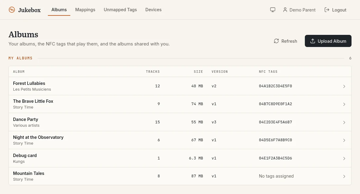
The SD card has a simple layout, so I can also prepare one by hand:
jukebox/
  settings.json        Wi-Fi and server settings
  mapping.json         card -> album cache
  state.json           volumes, last album and track
  system/startup.mp3   optional boot jingle
  albums/<id>/         manifest.json, journal, 001.mp3 ...
  logs/boot-NN.txt     last 4 boot logs
The display only has four seven-segment digits, so everything has to fit
in four characters: a moving bar when idle, dL42 while downloading,
07 for the track, U50 for the volume, and short error codes such as
E-1F when the Wi-Fi fails or E-nr for a card that is not registered.
Children do not read them, but they help a lot when a parent has to find
out why nothing plays.
The first generation
The first version ran an Arduino firmware on ESP-IDF 4.4, with ESP8266Audio for the MP3 decoding. The first prototype had rotary encoders for the volume and the tracks. In March they were replaced by push buttons on a first real board, rev 1.0, in a FreeCAD case.
The encoders were too hard for a child to control: it is difficult to turn one by a precise amount, so a push button is much easier for small hands.
It worked, mostly. But over the summer each fix seemed to move a bug somewhere else. In October I read the whole firmware, about 9,400 lines, and listed what was wrong. Three choices explained most of the problems:
- Everything slow ran in one 100 ms control loop. The Wi-Fi connection, the card lookup and the whole album download ran inside it. During a three-minute download, only the volume buttons worked.
- The tasks talked through five volatile booleans. Two presses in one tick became one, and next and previous in the same tick became next.
- The audio task busy-spun. ESP8266Audio writes to I2S with a zero timeout, so when the DMA buffer was full the loop returned at once and core 1 ran at 100 %, also draining the battery.
Around these, there were plenty of smaller ones. Pause was implemented as
stop, so play restarted the song from the beginning. Downloads had no
resume, so a Wi-Fi hiccup at 79 MB of an 80 MB album threw the whole album
away. The download progress was computed as bytes * 100 in a uint32_t,
which overflows above 42.9 MB, and four of my twelve albums were bigger
than that. HTTPS was used without any CA, so the client silently fell back
to setInsecure(). And the “atomic” file write deleted the target before
renaming the new file, so an unlucky power cut could make the box forget
its Wi-Fi.
None of these are hard to fix one by one, but fixing them in that structure would not have made the next bug any easier to find. So I decided to rewrite it.
Then the first box was broken by a bad connection, and I decided to focus on finishing the second version, the one the kids use now.
A firmware rewrite on ESP-IDF
The new firmware is plain ESP-IDF 5.3 in C++17, without Arduino. The rule was the same feature set on the same hardware, with only the behaviours that were really defects changing: pause is a real pause, the end of an album stops instead of looping forever, and tapping another card while playing switches album.
The structure is the main change. Every task (buttons, NFC, network,
display, audio) posts small fixed-size events into a single queue, and only
the controller reads it. The controller is a pure state machine
(Booting, Idle, Resolving, Preparing, Playing, Paused,
Error) that turns events into a list of actions, and a separate piece of
code executes them through non-blocking component APIs. The controller
itself never touches the SD card or the network, so it can be tested on my
workstation: the firmware has more than 430 host unit tests, and the
server more than 100 pytest cases, including a check of the device API
against its OpenAPI contract.
The download pipeline was also rebuilt. Tracks are fetched in chunks with
HTTP Range requests and hashed while they are written. A journal per
album records what is done, so an interrupted download resumes on the next
tap, and a power cut never leaves a corrupt album behind. Files are written
to a temporary name and renamed, without deleting the old one first.
The box also got a task watchdog, a core dump written to the SD card, and
over-the-air updates with rollback: a new image is only marked valid once
the controller reaches Idle.
Running out of memory
The hardest part was not the code but the memory. On the rev 1.0 board, the SD card is wired to GPIO35, 36 and 37, which the module also uses for its octal PSRAM. So the PSRAM had to stay off, and everything had to fit in the internal RAM.
The first measurements on the real board were bad: the application started with 266 KB free, but with Wi-Fi up and the audio buffer allocated, only 37 KB remained, with a minimum of 788 bytes during the first HTTPS request. To find where the memory went, I added a heap ledger that records the free heap around each initialisation step. It showed some expected costs (audio 60 KB, Wi-Fi driver 34 KB) and one surprise: mounting the SD card cost 42 KB.
The culprit was the FATFS sector size, which defaulted to 4096 bytes: eight file buffers of 4 KB each. Setting it to 512 bytes brought the mount down to 9 KB. The other big win was mbedTLS. Its dynamic buffers allocated one block per TLS record and fragmented the heap until the next record buffer did not fit anywhere, so nearly every download chunk had to reconnect. With static buffers of 16 KB in and 4 KB out, held for the whole session, the box now has 128 KB free when idle with Wi-Fi up, and the downloads stopped failing. A “playback gate” also keeps the network and the audio apart: an album is fully downloaded before it starts, and the background checks only run while the box is idle.
Testing on the bench
To validate all this on real hardware, the firmware has a bench build with a small command console on the USB serial port, and a pytest harness that flashes a board, drives it through the console and writes a report. The rollout was split into gates:
| Gate | Checks | Result on the rev 1.0 board |
|---|---|---|
| 0 | Boot, SD card, NFC reader, watchdog, stacks | Boot to idle in 312 ms |
| 1 | Playback from the card | No underrun on a 16 KB ring buffer |
| 2 | Cards and buttons, offline | Tap to playing in 130 ms |
| 3 | Network: lookup, download, resume | A track resumes after a 3 s Wi-Fi drop |
| 4 | Soak: 100 cycles of tap, play, stop | Same minimum free heap in the first and last cycle |
The gates found real bugs before the children did: a body shorter than the HTTP header buffer reported as empty, a core dump partition too small for a corrupted stack, or a task stack sized from idle measurements that overflowed on its first real save.
The rev 2.0 board
The rev 2.0 board was designed with the case, and it fixes the hardware constraints the rewrite had to work around.
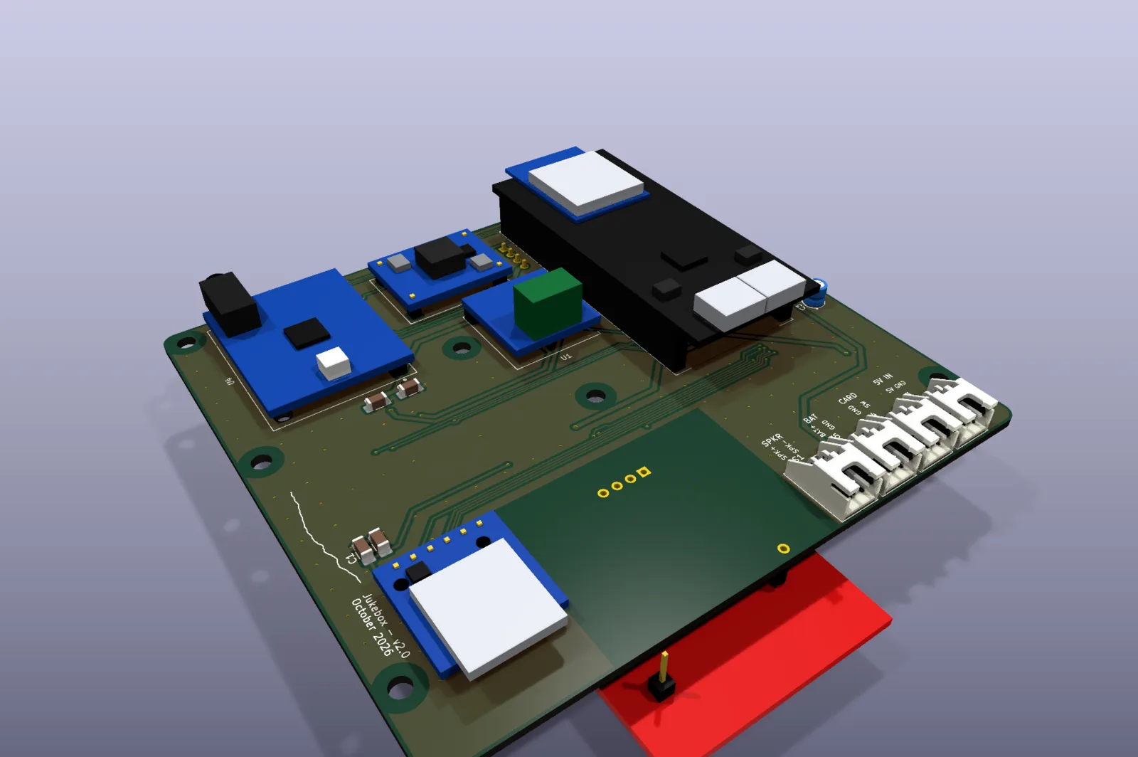
- The SD card moved to GPIO1, 2 and 42, so the PSRAM can be enabled.
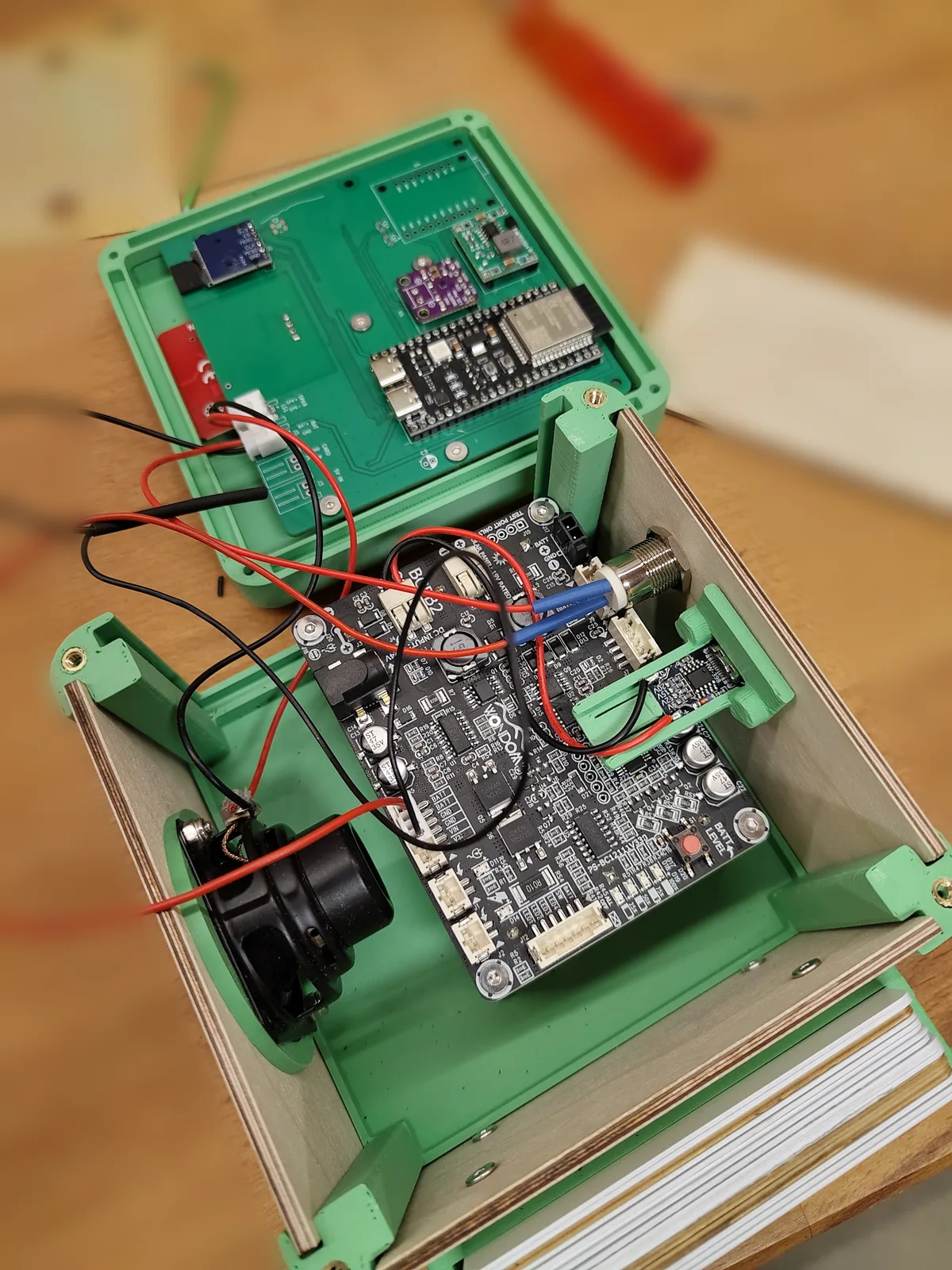
- The board is mounted upside down. The buttons and the display are on the bottom layer and face the top of the box, while every module hangs underneath. All connectors are JST-XH on the front edge, instead of Dupont wires.
- Two DAC options. Either a MAX98357A (speaker only) or a TLV320DAC3100 breakout, which adds a headphone jack with automatic switching and a separate volume for each output. The firmware has a build for each.
- The PN532 plugs straight into the board instead of hanging on a harness, and an optional MP1584 buck converter makes the 5 V from the battery.
The PN532 change came with a nice discovery. The old harness connected the reader’s reset to the pin labelled RSTO on the module’s header. That is the reset output. The reset input, RSTPDN, is only available as a small pad at the end of the module’s 1.27 mm pin row. So the hardware reset of the reader had never worked, and the firmware’s “reset the reader when it stops answering” could not have helped. On rev 2.0, a thin pin soldered into that pad plugs into a dedicated socket on the board.
The battery is a Wondom BCPB2 board with three 18650 cells. It is a battery holder, charger and protection board in one, and it sits inside the case, so the kids cannot get to the cells. It has no USB, so charging goes through a USB-C power delivery trigger fixed at 15 V on the back of the box, next to the latching power button.
The first rev 2.0 board is built, with the MAX98357A.
The next step is to explore using the PSRAM available on this board to improve its features, once my kids have tested everything in depth.
A case generated by a script
The case had two requirements: survive children, and fit the board exactly. It is a printed frame with laser-cut 4 mm plywood walls.
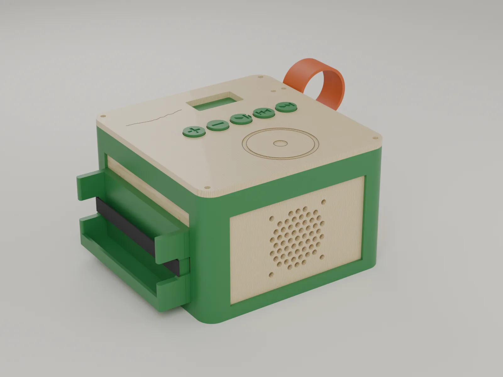
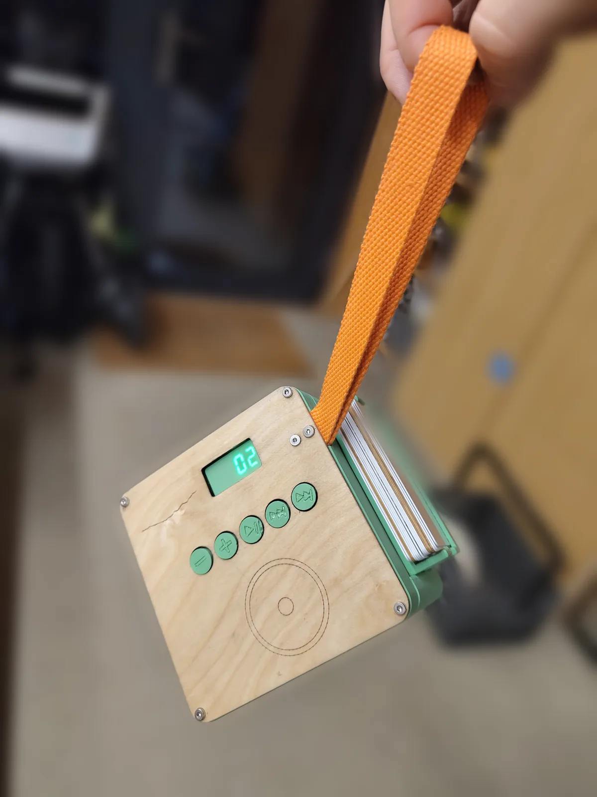
The speaker sits behind the front wall, under a grille of holes no larger than 4 mm with a stainless mesh behind it, so a pencil cannot reach the cone. The buttons are captive printed caps: they are dropped into the top from below, and the board holds them in place. The display shows through a single printed layer of 0.2 mm, and the NFC zone is an engraved ring above the reader’s antenna. A loop of webbing on one side makes it easy to carry, and the card pouch on the other side holds about fifteen cards with an elastic band.
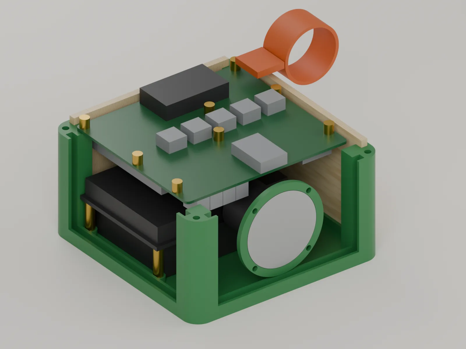
The whole model is generated by a Python script running in FreeCAD 1.1.
It only uses PartDesign primitives, pads and pockets on constrained
sketches, and every dimension is a cell in a Params spreadsheet, so the
model can still be opened and tweaked in the GUI. The interesting part is
that the script reads the KiCad board file: the positions of the buttons,
the display, the mounting holes and the jack are taken from the PCB, so
moving a button on the board moves its hole in the lid. It even detects
that the board is mounted upside down, from the display being on the bottom
copper layer, and mirrors the coordinates.
A make check step then loads the model and checks the board against it:
the board size and holes must match, no part may overlap another one, and
there must be enough room behind the speaker. It caught several real
problems, like the ESP32 DevKitC being 5.5 mm longer than its footprint,
which put its antenna against the back wall. The board now sits 2 mm
further forward, and the check fails if the antenna gets closer than 1 mm
to the wall.
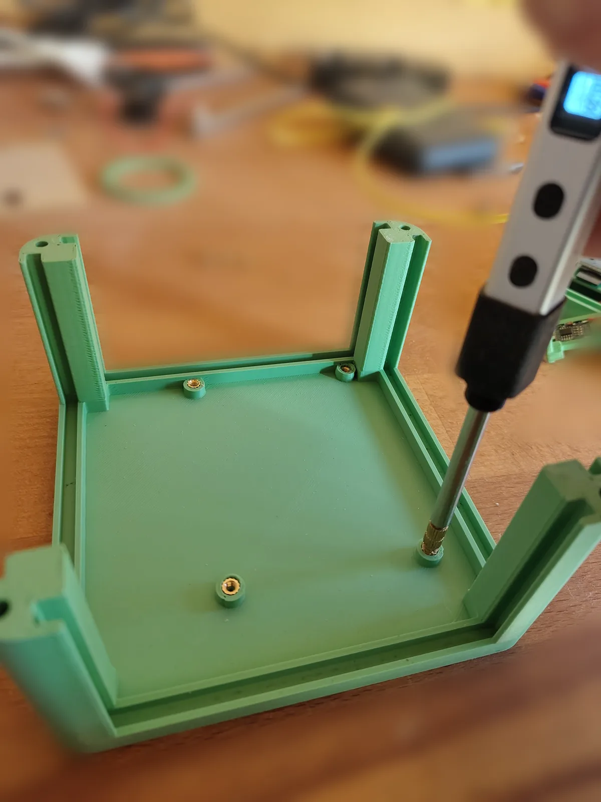
Long printed pillars tend to split along their layers, so I avoided them: the board hangs on brass standoffs screwed into heat-set inserts, and the battery board sits on 18 mm standoffs on the floor.
The plywood panels come straight from the laser files of the build: the top with the button holes, the display window and the engraved NFC ring, the front with the speaker grille, the back with the openings for the power button and the USB-C holder, and the two sides, one of them with the screw holes for the card pouch.
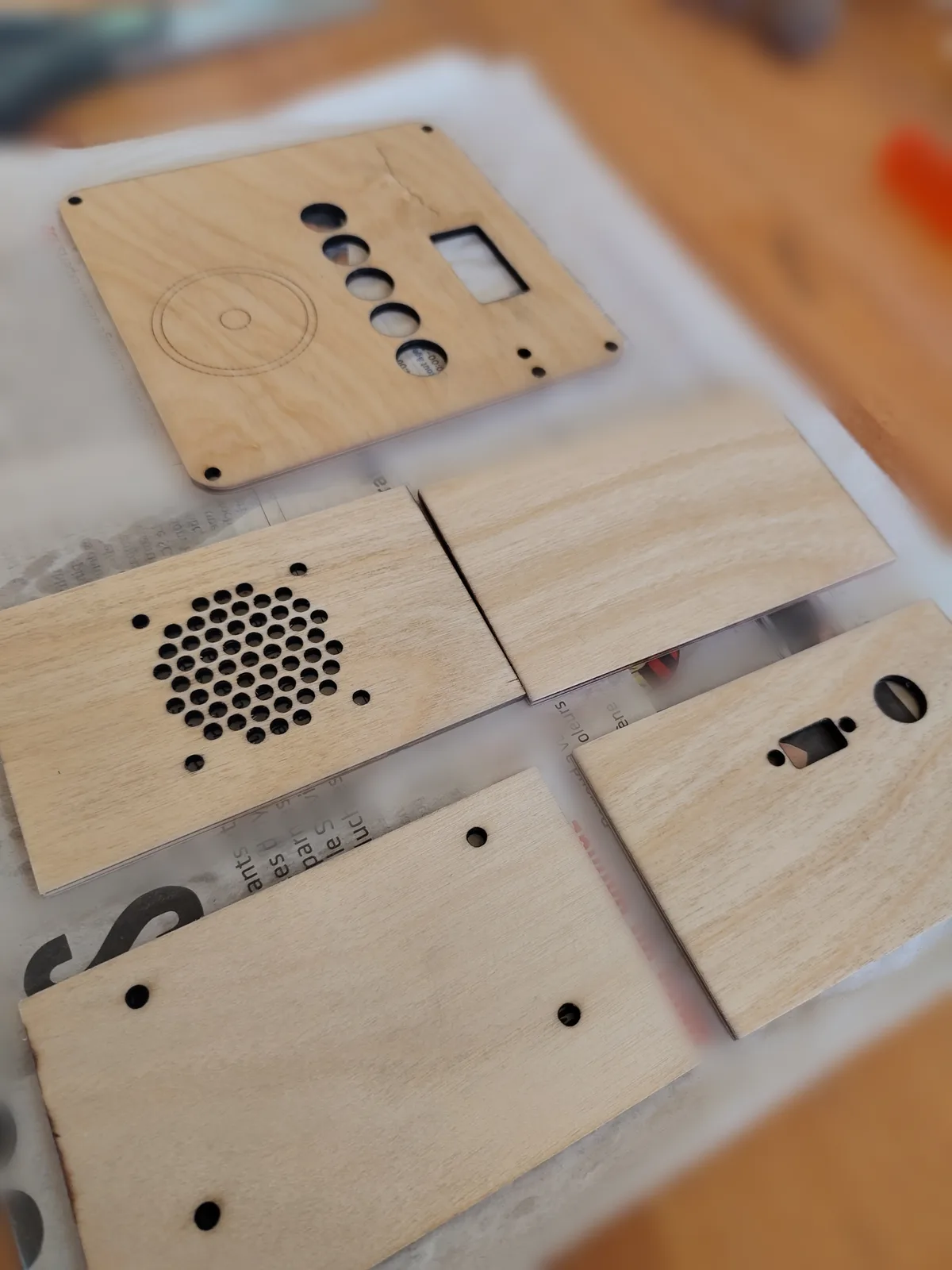
Printing and cutting went without any problem. The top panel has a skyline next to the display: the mountains we can see from our home, including my kid’s favourite one.
Conclusion
The jukebox ended up touching almost everything I like to do: firmware, a board, a case, a small web service and a deployment in the lab. The rewrite was the most useful part. Splitting the firmware into an event queue and a pure state machine made it testable on my desk, and the heap ledger turned “out of memory” from a guess into a table of numbers.
The repository needs a little cleanup and the case a few small tweaks first, and then I will publish it. That should be soon.
The next steps are to explore using the PSRAM available on the rev 2.0 board to improve its features, such as downloading faster and playing while downloading, and to assemble the TLV320 variant with a headphone jack. That one will even let them each listen to their own story with headphones in the car. I also want to build a second rev 2.0 box, in a different color, so that each of them has their own.
For now, the kids love it. They listen to stories with it before sleeping, and to music when they are playing or when they want to dance. I have not measured the battery life exactly, but it is long, and nothing has broken yet.